Computer-Aided Design (CAD)
All of the CAD for this robot was done in Onshape in order to make collaboration and accessibility as simple as possible. We made detailed CAD models for each component of the robot to make the fabrication and assembly process seamless and fast and to ensure that each component was as easily manufacturable as possible.
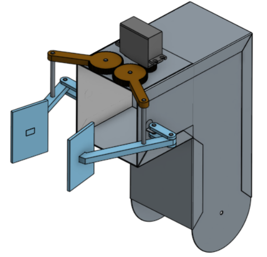
Arm Model
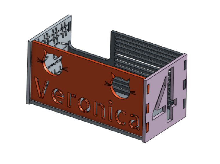
Basket Model
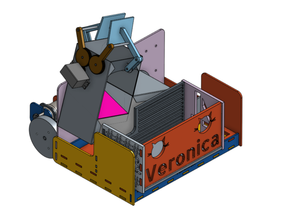
Assembly Front View
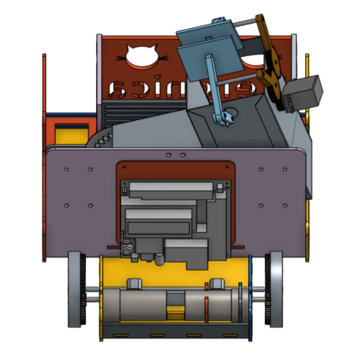
Assembly Rear View (Drive System)
Chassis
The chassis was constructed using pieces of laser cut hardboard which were press-fit together to ensure that the build was strong, stable, and quick to assemble. A large amount of time was spent in the CAD stage of the design to make sure that the pieces fit together as precisely as possible.
The electrical system was centralized on the back divider of the chassis using racks of PCB’s (Printed Circuit Boards) to maximize accessibility in the case of electrical failures and troubleshooting.
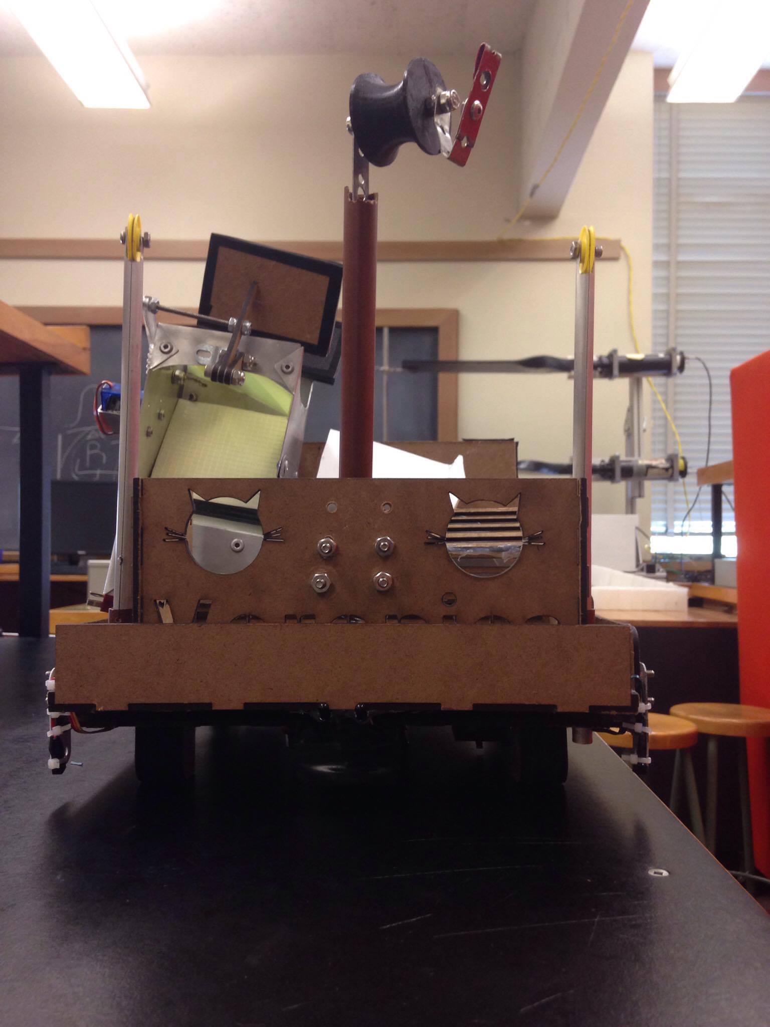
Front view of chassis with basket

PCB (Printed Circuit Board) racks
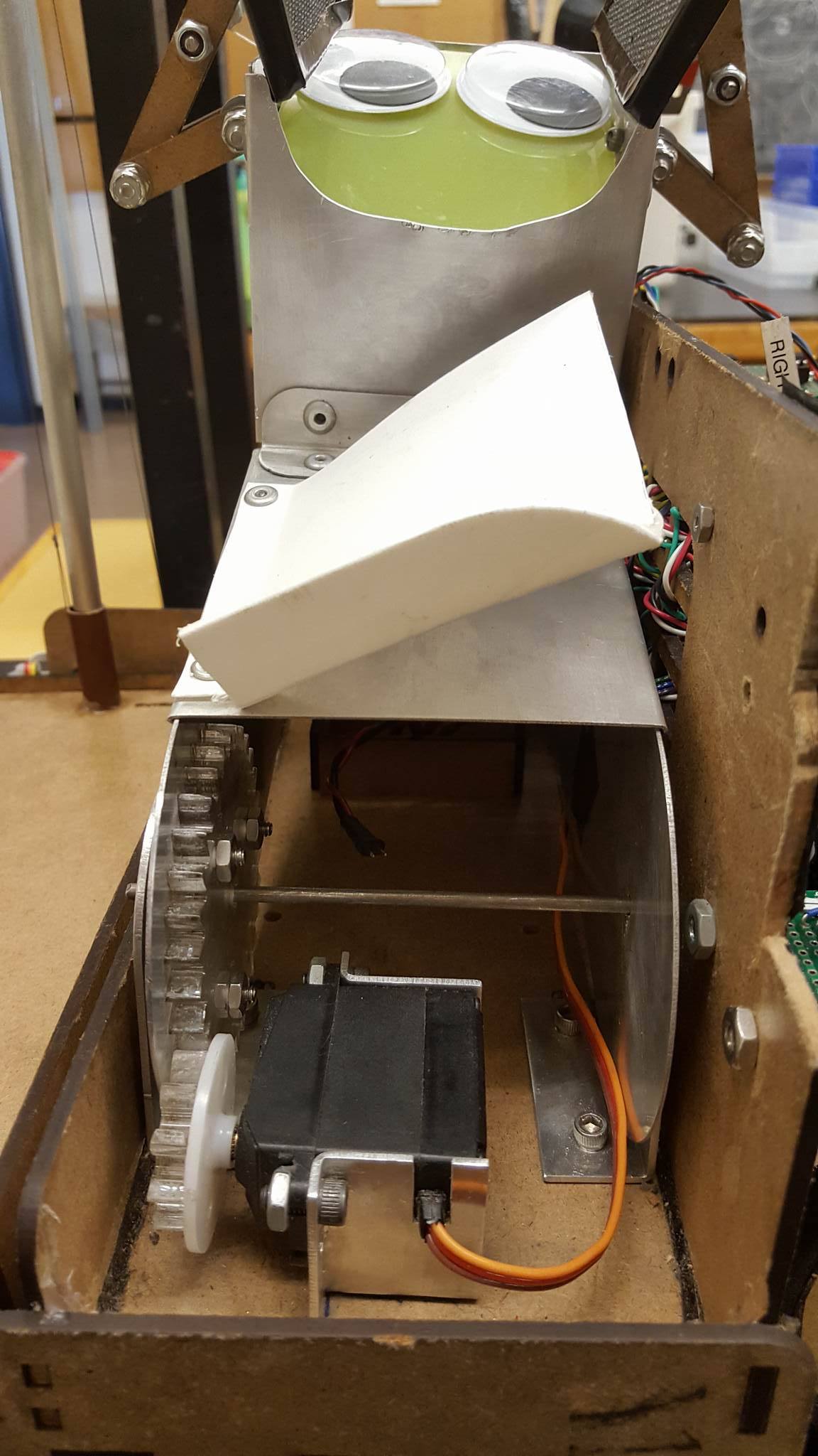
Mounted arm on chassis
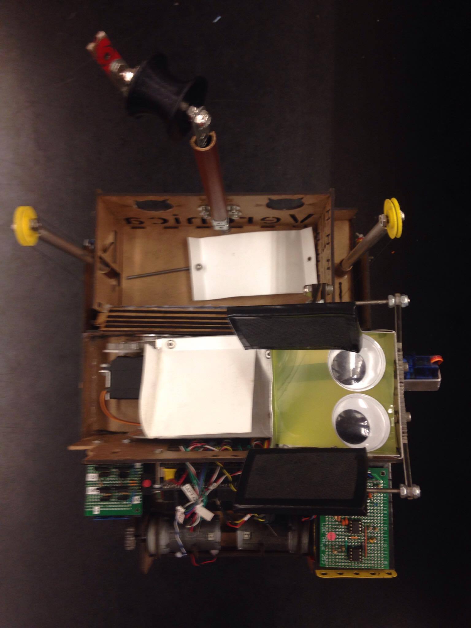
Overhead view of chassis
Arm
The arm was designed to maximize its limited space on the chassis and to make the retrieval of agents as simple as possible. It was constructed out of water jet pieces of aluminum that were bent and riveted together to ensure that it was stable but light enough to be raised and lowered quickly, and the pincers were made of laser cut hardboard.
The idea is that the agents will be retrieved with the pincers and then would fall straight through the arm into the basket in order to eliminate unnecessary motions.
Both the arm and the pincer are actuated by geared servo motors. The arm is raised and lowered using a 3:1 gear ratio made of 6mm thick PMMA plastic, and the pincer is opened and closed using a 2:1 gear ratio made of laser cut 3mm thick hardboard. The linkages for the pincers were assembled using locknuts to eliminate the possibility unscrewing from the torsion of the opening and closing motion as well as to make replacement easy in case the linkages broke or needed to be replaced.
Our earliest iteration of the arm struggled with agents getting stuck in the chute. Eventually we moved onto a slide system which was much more reliable.
Our second implementation of the arm was more consistent, but some agents still got stuck. Our final iteration includes a second slide that blocks the chute.
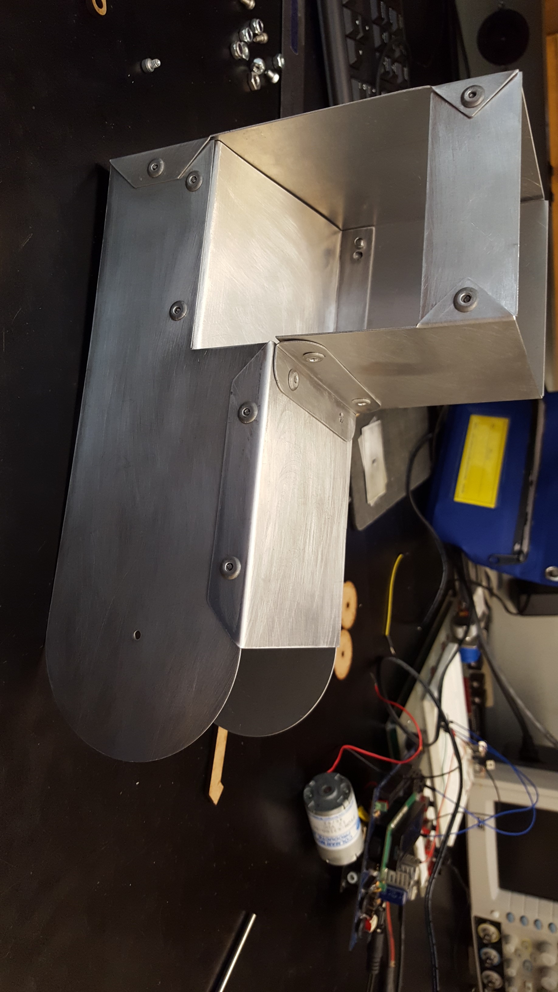
Assembled arm before being mounted
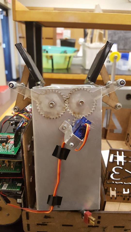
Pincer servo and gear mechanism
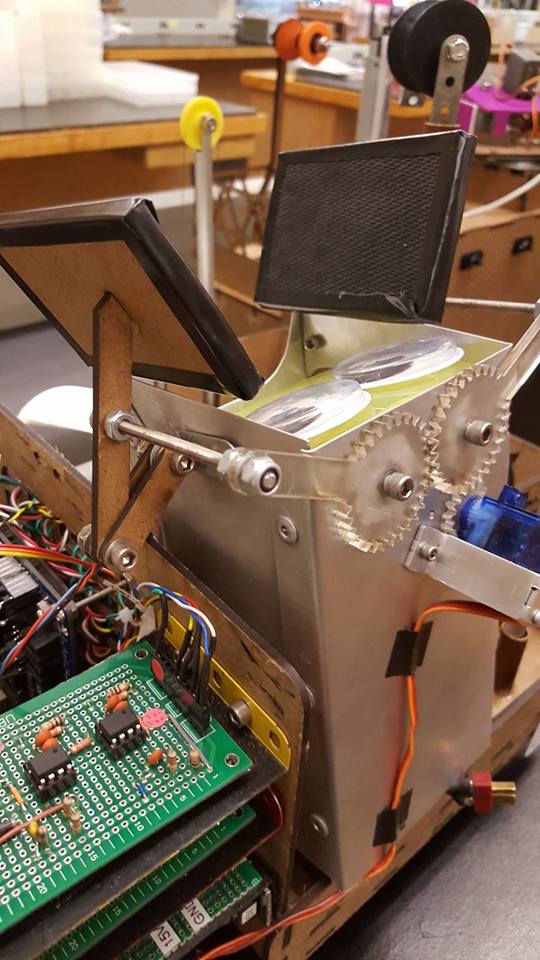
Pincer and paddles for picking up agents
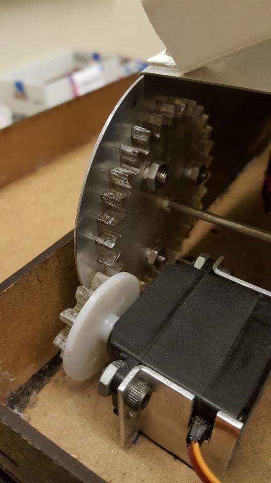
Close up of arm actuator system
Zipline and Lift System
The lift is actuated using a winch / pulley system and a servo motor that was modded for continuous motion. This was designed for fast and easy assembly as well as to maximize the amount of height gain in the smallest amount of space on the chassis.
The zipline basket is made of laser cut hardboard that was press fit together. The designs and cut outs were partially for aesthetic purposes, but also to make the basket as light as possible. In order to reduce the accuracy needed for locating the zipline, the hook for the basket was spring loaded so that it could slide onto the bar from any angle. The spool was 3D printed to perfectly fit the contour of the zipline bar.
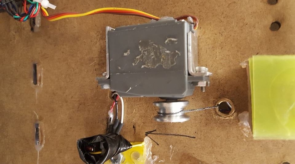
Modified servo mounted under chassis
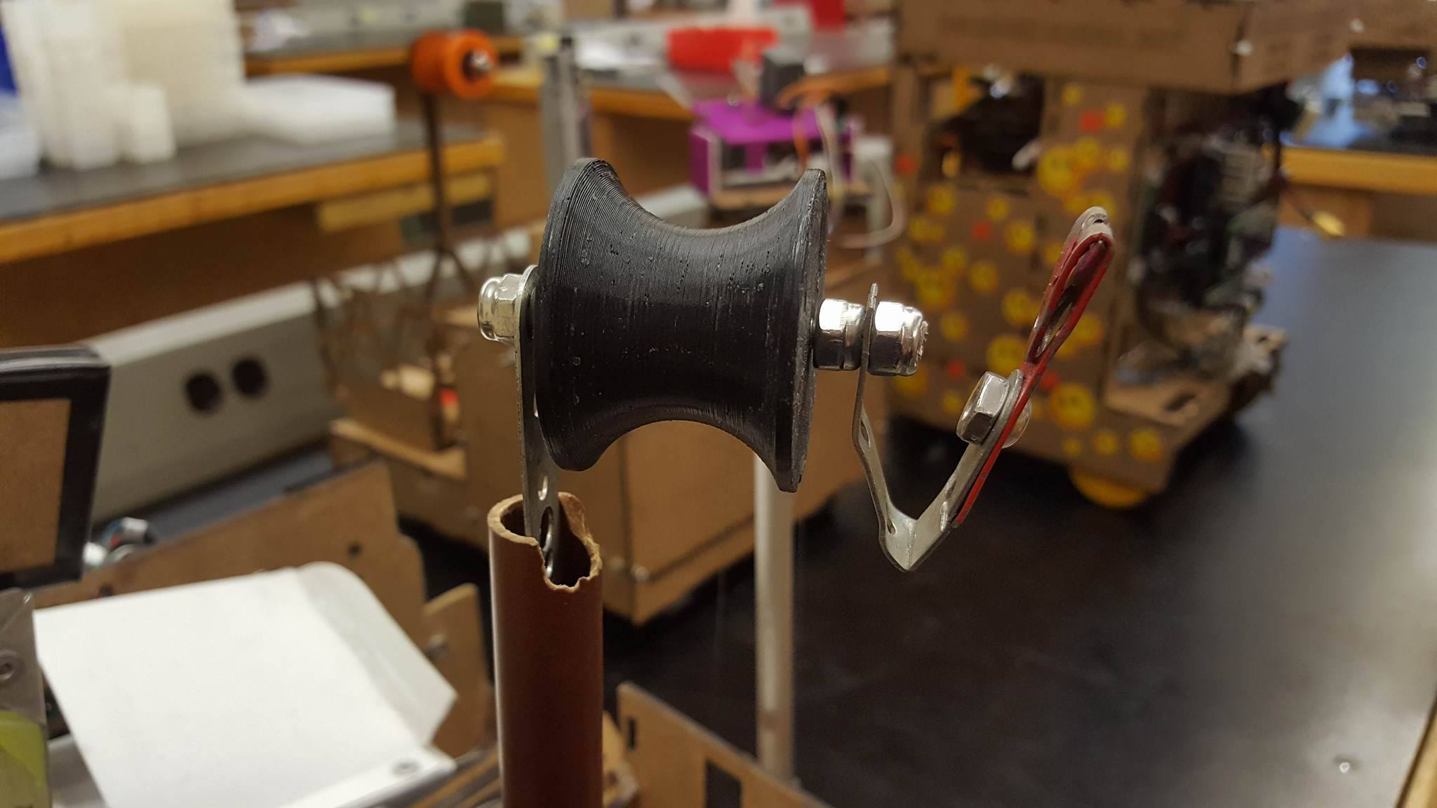
Spool which attaches to zipline
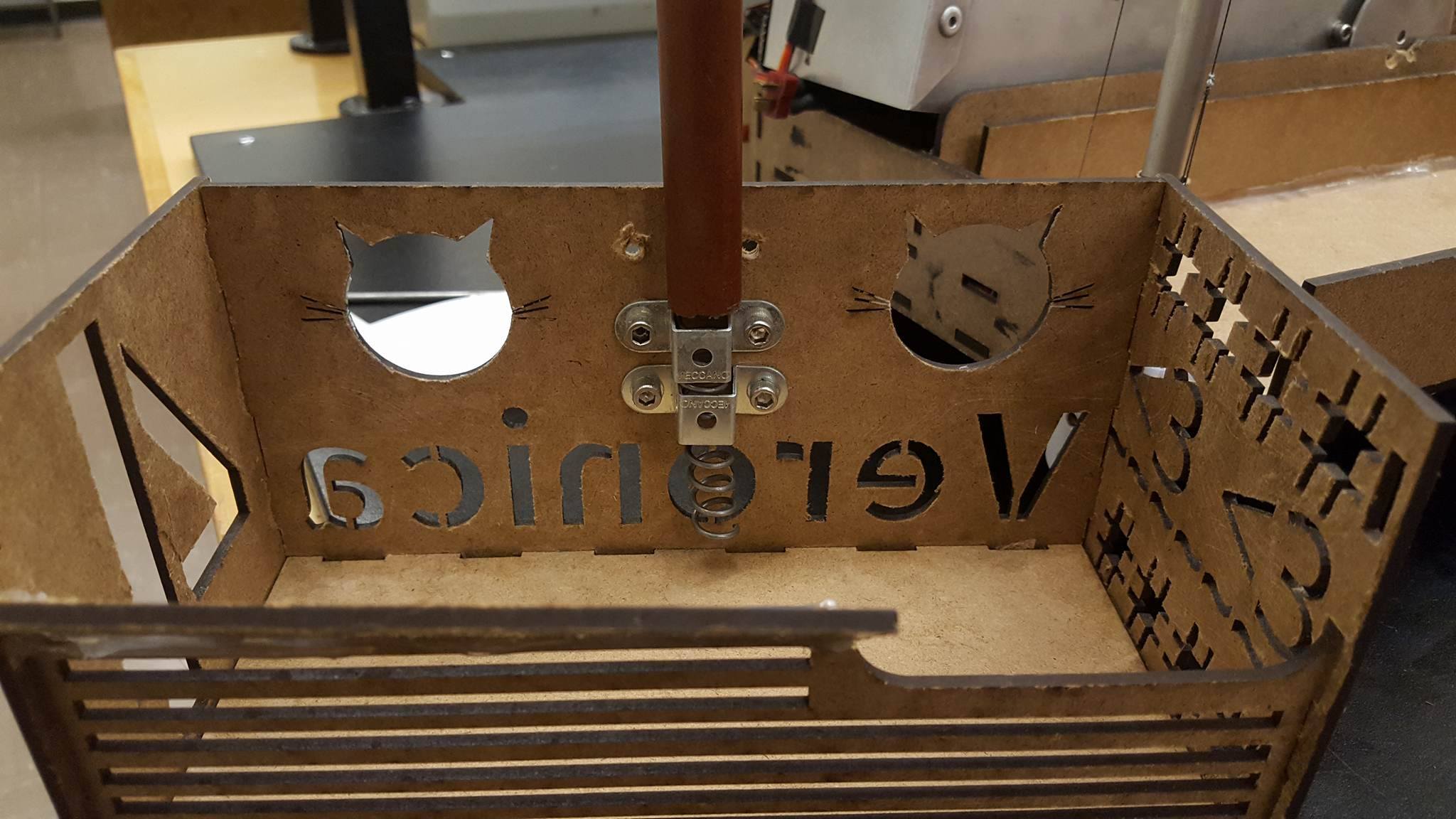
Inside view of basket
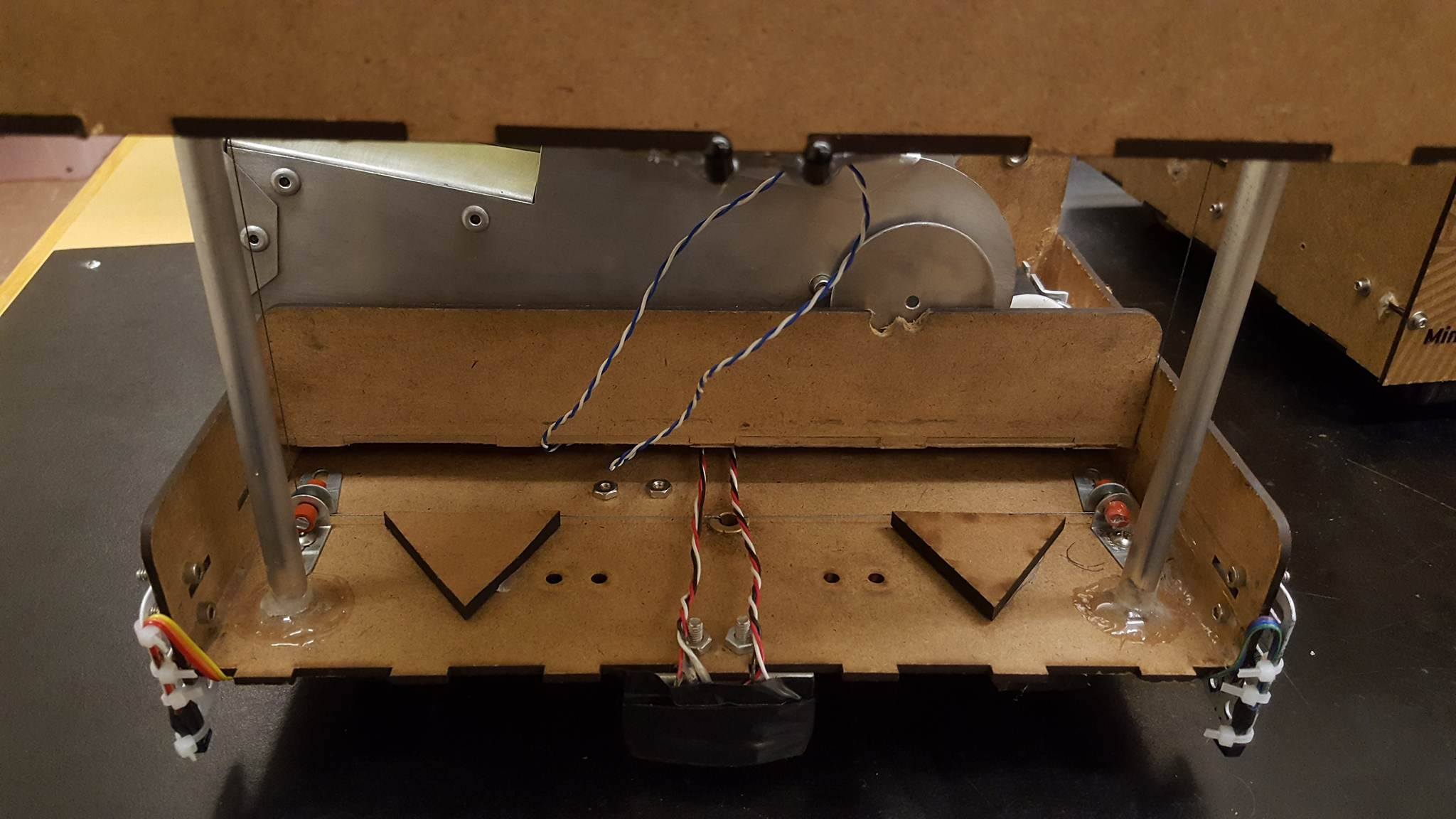
View underneath raised lift
Fabrication Techniques
Our major fabrication methods were laser cutting and waterjet cutting. These methods were ideal because they ensured fast manufacturing and prototyping given, as well as precise fitting parts. This was essential for the assembly of the chassis which was constructed using laser cut pieces of hardboard that were press-fit together.
The body of the arm was made out of water jet pieces of aluminum, and all of the gears for the pincer and raising and lowering of the chute were made of laser cut PMMA and hardboard.
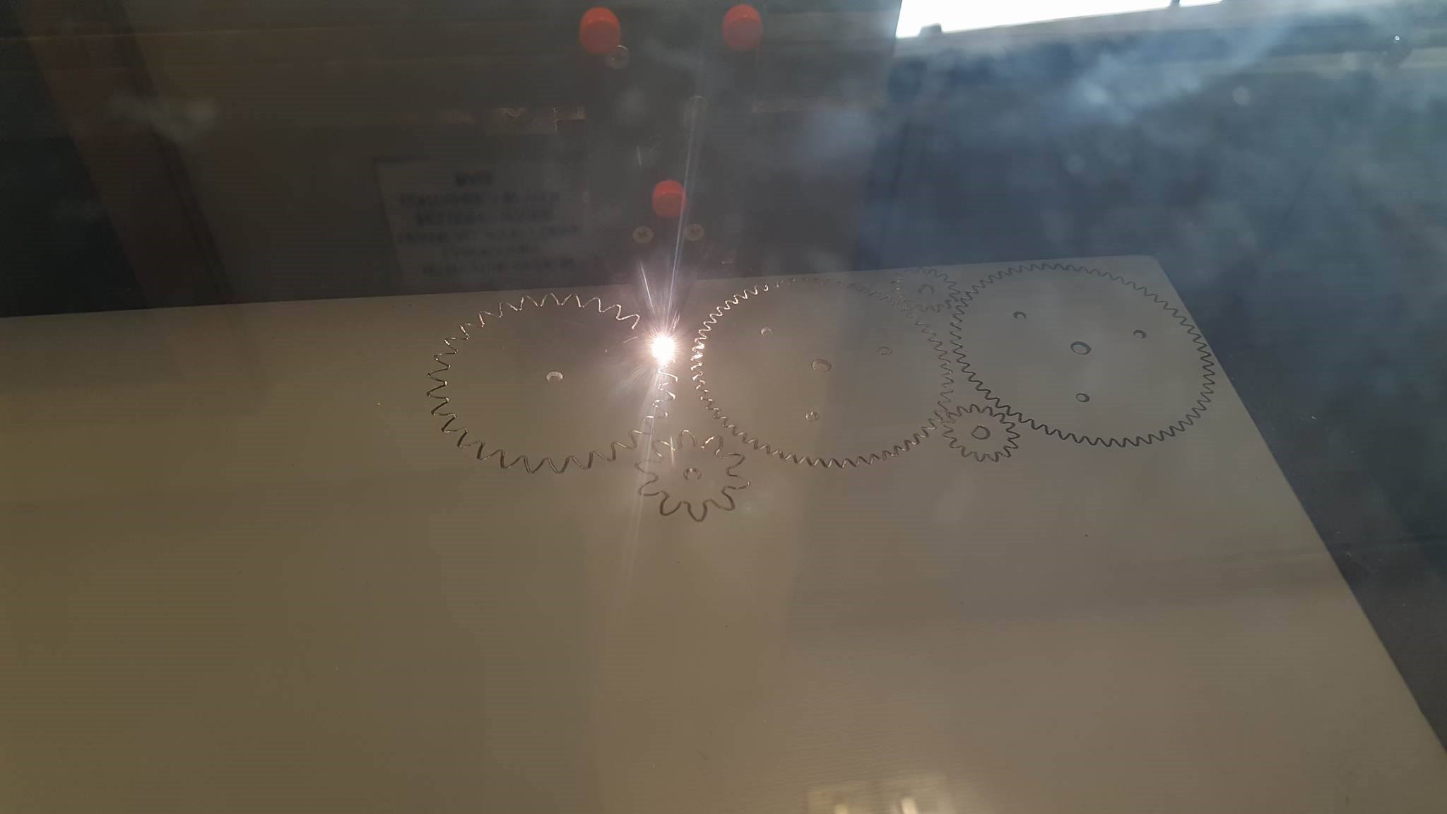
Laser cutter cutting acrylic gears
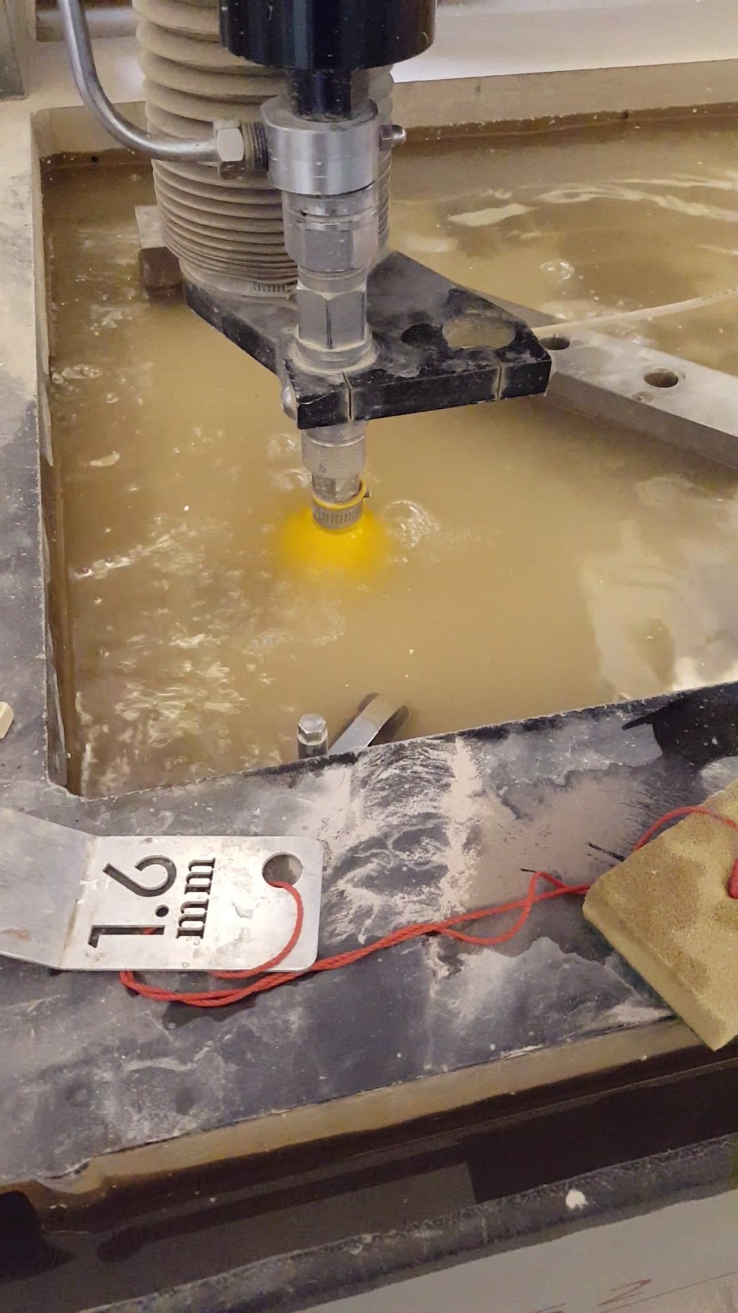
Waterjet cutter cutting metal parts
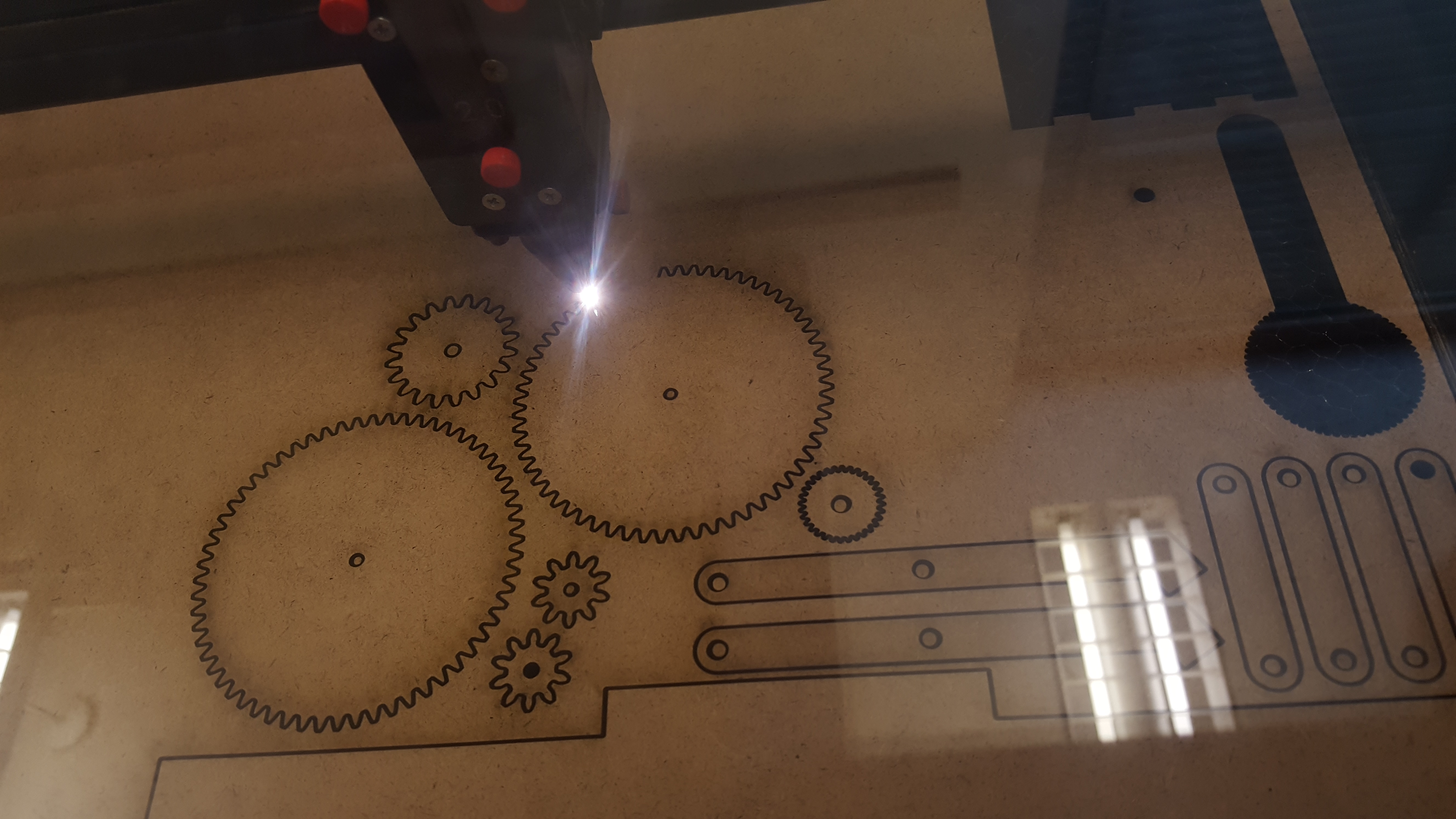
Laser cutter cutting hardboard gears and linkages